|
|
Electrical
This section details all things electrical. In it I'll discuss the various
bits of electrical work done, as well as detail other activities (like
classes, etc.) that impact the electrical and wiring portion of the project.
In some of the following entries you'll see me NOT entering time spend on
the effort. This is because the electrical work was incidental to other
activities being performed (like installing the flap actuator assembly)
and time spent is logged elsewhere.
| Pulled Coax through Wings |
October 8, 2004 |
|
You can see the details over in the Wing section of the builder's log,
but in a nutshell I pulled the COM and NAV coax runs through the wings.
Hours for the effort are accounted for in the other section of my log.
|
| Installed Roll Servo Wires |
October 10, 2004 |
|
Again, you can see the details over in the Wing section of the builder's log,
but in a nutshell I installed the roll servo in the right wing and
brought the control/power wires out to the wing root. Hours for the
effort are accounted for in the other section of my log.
|
| Terminated Flap Controller Wiring Harness |
September 23, 2005 |
|
Detailed in the Fuselage section, I used my new handy-dandy Mate-N-Loc
pin crimper to install a 4-pin Mate-N-Loc connector on the flap motor
controller. Once I used Google to find a data sheet on the crimper, it
worked like a champ.
|
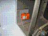
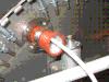
| ANL Holder Installed |
November 6, 2010 |
|
I'm finally back to working on stuff after another week in San Jose (and
it seems a week recovering from the trip). The trip was due to my group
winning a major company award and attending the award ceremony. I may even
put a picture of me in a tux (yes, this was a fancy-pants big deal sort
of event) up on the website. Then again, maybe not. :)
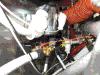
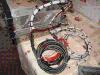
Tonight I got out and worked on some wiring again, this time installing
the ANL holder I got from the B&C folks. I decided where it needed to go
on the firewall, drilled for the platenuts, installed the platenuts (with
help from my #1 riveting helper, Theresa), and mounted the holder. I also
used a random #2 wire from the Van's wiring kit to jumper from the ANL
holder to the ammeter shunt. I need to cut the B-lead wire to length and
crimp the connector, install the wire, and then that bit of work will be
completed.
Time : 2.25 hours |
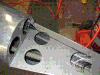
| VP-X Installation Brackets |
December 4, 2010 |
|
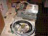
Last week I received a Vertical Power VP-X empty enclosure so that I
could work through the installation of the box in the RV. It is VERY
cool that they do this (for a $100 deposit) as it lets builders get
some mechanical work out of the way _before_ having to spring for the
electronics themselves.
A good bit of time was burned in head-scratching and test fitting
various things. I had a few criteria I wanted to meet. First, I wanted
it to be the case that I could easily get to the connectors (as easy as
access to anything up under the panel can be, at least) once the box
was installed. I also wanted it to be such that I could mount the box
by installing a few screws pointing straight up (so that on my back
in the fuselage it would be a straight shot to the screws). I also
wanted it to _not_ encroach on any area behind where the radio stack
will go so as to avoid the possibility of a deep radio tray conflicting
with the VP-X installation.
I found a spot on the pilot side right in line with the forward upper
fuselage rib. I am _very_ pleased with the location. I didn't get quite
done with installing the brackets today. I still need to install four
nutplates, need to prime the brackets, and then rivet everything in
place. Then it'll be a done deal.
One final note .... it _snowed_ today! For us this is a rather early
snow. There is some accumulation on the grass and bushes and trees,
but little (if any) on the roads. That said, it is supposed to get
down to 28 tonight so it might end up a bit icy in the morning. Good
thing I have airplane parts to work on, isn't it? :)
Time : 4.0 hours |
| VP-X Installation Brackets / COM Antennas |
December 5, 2010 |
|
Today I finished up the install of the VP-X brackets. They are solid
enough that I think I could lift the plane with them (which probably
means I overbuilt them ... oh well). But I'm fairly happy with the
location I found, and how it all worked out. It'll never be fun trying
to work on something overhead, laying on the floor of the cabin,
in that oh-so-tight area. But this will be about as good as it is
going to get. That said, it seemed to take forever wrapping it all
up.
I also installed the two RAMI AV-17 antennas on the belly of the
plane. This, too, went slow because I wanted to be sure they were
_right_ before drilling holes that would be a pain to close back up
if they were wrong. I got help from Marie to run the nuts onto the
screws while I lay on the floor to tighten everything up. They look
sharp, and are ready to hook up as soon as I have radios in hand.
I did NOT get around to doing the last bit of work I wanted to do
on the baffles. That will be the next task.
UPDATE: My pictures of the VP-X install got included in a Vertical
Power newsletter as examples of a good installation. Way cool. :)
Time : 5.0 hours |
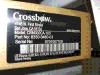
| ELT Install |
December 29, 2010 |
|
I received my ELT yesterday, and started the installation today. I
elected to go with the "old style" 121.5Mhz unit, and picked the
AK-450 since it is (a) simple, (b) takes D-Cell batteries, and (c)
will make me "legal". I honestly think ELTs have little value, and
while I'm going to install it and won't be offended if it saves me
one day, I'm also not counting on it. To that end I'm also going
to run an APRS ham rig (and I _do_ have my ham license, KJ4ECK, for
the curious) which will continuously track my position (i.e. it will
leave "breadcrumbs" on the APRS tracking websites). I'll also be
carrying a 406Mhz PLB. No, it won't trigger based on a G-switch, but
it will give me all the other 406Mhz advantages for a fraction of
the price of a 406Mhz ELT.
'Nuf said on that ... my logic is mine, and you can agree of disagree
as you see fit. The install itself was more timely than I expected.
The latch on my unit was .. well .. wrong. I had to fiddle with it
to make it right. Then they wanted piddly-ass #4 screws, but the
smallest I countersunk screws I had were #6s. So I opened up the holes
and tweaked the countersinking so I could use #6s instead. I also
had to figure out where to install the antenna, which leads me to
the next controversy.
I am putting it in the tail, under the fiberglass fairing. Pros and
cons with this location, but I think the pros outweigh the cons. I
honestly think the traditional external mounting location is stupid
as it is just as likely to get sheared off as anything else. In the
back it is blanked somewhat by metal (but it would be blanked a bit
if it were mounted on the top of a plane that ended up on its back)
but others have reported good signals from that location even with
the metal. The upside of this location is that it is likely to stay
intact in a crash.
I still need to run the coax, because this is a slightly longer run
than they anticipated. I also need to finish fishing the remote cable
to the front of the cabin. That'll happen tomorrow. For now ... I'm
gonna go fly. :)
Time : 4.5 hours |
| ELT Remote Cable Install |
December 30, 2010 |
|
I was going to work on the RV today, but ended up spending time on
the Citabria instead. The battery, which had been getting weak, finally
croaked. Totally. So I drove to Lexington NC (would have flown, but I
did not want to get stuck on the ramp in Lexington if the jumping of
the battery did not leave it with enough juice to give me one more
start to get home again). Why? Well, the
Airparts people are there and
they had the Concorde RG-25 battery I needed in stock. This was to
replace the old Gill G-25. Wow ... is this battery ever strong. I
don't remember the Gill ever having this much enthusiasm.
That said, once I got the battery in the Citabra I had to fly. That
burned an hour of time, and eventually I got home from my very long
day .. and spent a LITTLE time on the RV. (We had guests coming over
in the evening, so my time was very limited.)
I did get some holes drilled in the seat ribs so I could pull the
ELT remote cable through and route it to the front of the cabin. I
didn't get the cable pulled ... just the hole for the snap-bushing
drilled. Pitiful, but better than nothing. :)
Time : 0.5 hours |
| More Wires Pulled |
January 1, 2011 |
|
There was much to do today (family activities, etc.) but I did get out
and pulled some wires from the back of the plane to the front. I got
the pitch servo wires pulled, and the ELT remote patch cable pulled.
This took a lot more fiddling than it should have, but I got it done.
Then I started to look at putting together the cables for my strobes
so I could pull them. First, I couldn't find the manual for the strobe
power supply. Frustrating, but not the end of the world. I figured I
would just to go the supplier website and pull down a copy.
Sadly, the supplier seems to have vanished. Lessons from that are :
- Never buy anything with electrons running through it until the very last instant you need it.
- Be aware than a non-major-supplier might just vanish, and don't be shocked when it happens.
The upside? This means I can move to solid state LED strobes and tail
lights now, rather than stick with the older xenon flash tube technology.
The downside? I gotta spend money I wasn't expecting to spend. BUT, I
can toss out that power supply and don't have to replace it with some
other one because LEDs just don't need big banks of caps to do their
job. Interesting, and all in all a win (except on the $$$ front).
Time : 1.5 hours |
| ELT Coax Run |
January 16, 2011 |
|
I blew most of my day dealing with a Citabria problem. We had a mic jack
in the back seat come loose, and fall into the sidewall. I got it fished
back out, and sorta-kinda reinstalled, but truth be told we need to
replace both of the rear jacks. I could fish out the existing one and
put a nut back on it legally, but really (I don't think) can't replace
it legally. We need to get an avionics shop to do the deed. (That said,
I really don't want to futz with pulling out the side panels, replacing
the jacks, and putting it all back together again anyway. I've got enough
airplane-stuff to do on the RV!)
However, in the scant amount of time I had left I did get the coax for
the ELT run from the ELT mounting location back to the antenna. I got one
connector on, but wasn't happy with my stripper ... so waited to buy a
new one tomorrow before doing any more coax connectors.
Time : 1.0 hours |
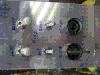
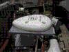
| Magnetometer Shelf / Firewall Passthrough |
January 17, 2011 |
|
Today I bought my stripper (and other odds and ends), and am very pleased
with the replacement. It is a 3-blade model and cut perfectly out of the
box needing no adjustments. I finshed the ELT coax installation, installed
the first of two firewall passthroughs (Safeair1 items), and fabricated the
shelf for the magnetometer. I fiddled carefully to get it within 0.2 degrees
of the angle of the panel (to match the EFIS), and within the lateral angle
of the fuselage.
Let me make a note here that I hate .. absolutely positvely hate .. cutting
holes in the firewall. I have trouble every freaking time I have to do more
than just drill a small hole. My Unibits "grab". My Greenlee punches always
_tear_ out the last little bit of metal, and get jammed. I hate stainless.
There. I said it. And I still have one more 1-1/8 inch hole to cut. *sigh*
Time : 5.25 hours |
| EGT/CHT/etc Sensor Wires |
January 23, 2011 |
|
Yesterday I flew a friend down to Spartanburg to have his Bendix system
looked at by Don Rivera. It was from a used engine, and it was quite
uncertain as to whether it was worth overhauling or not. As it turned
out a careful examination by Don revealed that it really was reasonable
to do the overhaul, and a deal was struck. It was a beautiful (but really
REALLY cold) day to fly.
Today I got out into the shop (after acquiring more propane for my shop
heater ... again, it is *cold* today) and started pulling the EGT/CHT
wires. I had to drill holes in the subpanel for the EFIS wire bundles
then pull the wires through the firewall (and sort them out neatly, and
once I get a quick question answered by the AFS guys it will be time to
install the connectors on the ends).
I also picked up some brass screws and nuts to use to secure the magnetometer
rather than the nylon screws I had used before. I feel better with the
metal over the plastic.
After lunch I identified and pulled wires for a number of engine sensors.
This entailed figuring out which wire was the wire-of-interest at any
given moment (color being the primary identifying trait), stripping the
end, checking the schematic to see which pin it should go to, and then
ohm-ing it out to insure I really _did_ have the right wire. I then routed,
terminated, and installed the wire. This also entailed installing about
a million and a half adel clamps to hold the wire securely as it found
its way through the engine compartment.
I did not get them all done, but did get the oil pressure, fuel pressure,
oil temperature sensors connected, and almost completed the fuel flow
sensor. I need to wrap that up, connect the RPM sensor, and then install
the EGT/CHT wires. Once that is done virtually everything FWF will be
completed. The only thing left will be to install my GPS antenna shelf
(with its coax).
Time : 7.75 hours |
| More Sensor Wires |
January 24, 2011 |
|
Today was not one of the best days. I woke up to a failed hard drive
on a work machine and feeling like I was coming down with something on
top of that. That said, I did get out in the shop for an hour or so
tonight which was good.
I finished connecting the fuel flow sensor to the wires I ran yesterday,
then sorted and ran a number of other wires. I was feeling so lousy I
didn't want to do anything "significant", so just satisfied myself with
getting wires identified and routed. I routed the RPM sensor wires, the
ammeter shunt wires, and the manifold pressure wires.
I still need to decide how I'm going to support wires running across
the inside of the cabin. I want to bear in mind that while I can reach
them fine-and-dandy now, in the future it will be me on my back trying
to get at the buggers. So, a short night of work, but at least I
touched the project.
Time : 1.0 hours |
| EGT/CHT Probe Wiring |
January 30, 2011 |
|
It was a light day on RV-building due to distractions. One distraction was
the first -really- -pretty- day of the year. Temps got into the high 60s,
the visibility (at least in the morning) was fabulous, and the winds were
non-existant. So I went flying thus blowing the morning. I came home and
did lunch with the family, and at lunch my daughter said she was really
ready to do some loops-and-rolls. So ... how could I resist? Back out to
the airport we went.
The place was a zoo this afternoon. We had little trouble getting out, but
by the time we were coming back there were multiple planes in the pattern
and on downwind we saw five lined up to depart! Wow. Taxiing on the
parallel taxiway we ended up nose-on with Cardnal, and since we could
turn around (gotta love a full-swivel tailwheel) we turned tail and went
back to another taxiway to let them pass. It was nuts out there, but I
totally understand why. :)
Anyway, I did get out into the hangar after I got back and put a few hours
in on the RV. Essentially I got the right-side engine EGT/CHT sensors wired.
The next side will go quicker because I have a routine established now. I
estimate I can finish the other side in half the time. Hopefully that will
happen tomorrow night.
Time : 2.0 hours |
| More Wiring (Surprised?) |
February 19, 2011 |
|
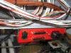
Today it was time for .. guess what? .. more wiring. No, I didn't think
you were surprised. I'm not either. I finished routing the main power
cable that will run to the VP-X Pro, and also finished routing the wire
for the nav/strobe light in the tail. I also terminated the magnetometer
cable with the AFS supplied DB-9 connector. I pulled the OAT cable back
out as the routing I was trying to use simply would not reach. I need to
find a way to route a few things (OAT, pitot line) down the left side
of the fuselage to behind the spar. It may be a bit tricky to do and
still keep things out of sight. Maybe I just should not worry TOO
much about the whole "out of sight" criteria. I will just have to see.
Other things that got done today were installing the spike-catching
diodes on the starter/battery contactors (after having to take almost
all that area apart to get the ring termials on .. its crowded down
there, and that took forever). I ran the EFIS ground wire, and for
those functions that were not going to be used on the EFIS I pulled
(and saved) the wires from the EFIS D-sub connector. Finally, I
took the VP-X mounting rails out of the fuselage, installed them
on the VP-X, and will finish mounting it tomorrow when I've gotten
some 8-32 socket head screws. They'll be easier to install/remove
in that tight location under the panel than would phillips head
screws. Or so it seems to me.
Time : 7.5 hours |
| VP-X Installed / More Wires |
February 20, 2011 |
|
Today I installed the VP-X Pro. It sure looks nice in that spot I
created for it. I also turned around the two screws holding the tank
vent lines realizing that once I close up the forward fuselage getting
a phillips head screwdriver on the head of the screw would be about
impossible. I'm in the mode of thinking about having to acess everything
under the panel from below .. and trying to make sure that is possible
in all cases.
I also installed an adel clamp to hold the wires which will run from
the switches to the VP-X, and fabricated the harness for the flap position
sensor. That was run to the VP-X and are the first set of wires to be
connected to the box. Wiring is now kicking into yet again a higher
gear!
Other work done today included pulling the flap motor wires forward,
connecting the flap motor ground to the central ground block, and
connecting the EFIS to the ground block. I got most of the way through
pulling the boost pump wires forward when .. after some small thing
went awry (truly not a big deal) .. my response was "arrrrrgh!". That
was my hint that it was time to call it a day. Even so, I got in a
good 7 hours so I'm not complaining.
One thing I've promissed myself I'd so is update documentation _as_
_I_ _go_, so that when I'm done the wiring docs are totally in sync
with reality. I had to stop a few times today to go up to the office
to verify details, and update documentation when I found issues. All
good stuff.
Time : 7.25 hours |
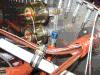
| Starter/Starter Announce Connected |
March 6, 2011 |
|
This morning I connected my starter and starter annunicator lines to
the VP-X. The annunicator line needed a resistor soldered inline, and
that meant I had to disconnect the wire from the "I" terminal of the
starter contactor. Getting into those contactors is a _pain_, as it
is really tight in that area.
I'm taking a break now to go help a fellow builder Ernest (building a
Dyke Delta). He needs to borrow my engine lift. Back in a bit ....
The post-lift-and-lunch timeframe was one of those "fits and starts"
afternoons. I first started into working on the aileron trim install
(should log it in another section, really, but since I wanted to get
it installed to further the whole electrical install exercise I'm
putting it here). I got the UMHW block drilled and trimmed, then went
to trim the mounting plate. I did it exactly as specified in the
instructions .... and it was, of course, too short. *sigh* I should
know better by now. So I'll have to order another one.
Another thing that has been needed is a connector to the battery to
allow me to connect a smart-charger. It took a few iterations to get
something I was happy with, and it is out there merrily charging right
now. This will allow me to start testing some electical circuits without
abusing the battery too badly.
In the spirit of being able to test electrical stuff without causing
grief .... I disconnected the wire from the starter. I don't want a
rogue signal causing the prop to start turning for ANY reason. While
I was messing with that I installed a pair of adel clamps to secure
it off the forward induction tube (something I've been meaning to do
for some time).
It doesn't seem like much ... but as I've said before, any progress
is good progress.
Time : 5.25 hours |
| Mock Up Engine/Critical Switches |
April 16, 2011 |
|
I have a vision in mind of what I want to do for my critical switches
(master, start, alternator, mags, and VPX backup), but wanted to test
the layout before committing to cutting AL. It took a bit of sketching
on a CAD program to get a layout, transfering it to some scrap AL, and
trying it out to see if I liked the spacing. Two tries did it which was
tedious but worth the effort. This will go to the left of the EFIS and
all the switches are used at start .. and generally not used afterward.
The one "oddball" is the Backup switch used to bypass the VPX for a few
critical devices in the event the VPX goes "toes up".
I need to make a decision on the switch guards. I'm not SURE that I want
to use them, but we'll see. They aren't really _needed_ as the start is
deactivated once the right mag is turned on.
As a side note, today we had a truly terrific line of t-storms come
through which spawned tornados across the central and eastern parts
of the state. I just had a run-in with tornados in Florida at SnF, and
having another set come near where I was in such a short period of time
is a bit surreal.
Time : 2.0 hours |
| VP-X-ing Today |
May 8, 2011 |
|
This was yet another weekend with a Saturday consumed by non-RV-building
activities. I flew a long (intentionally solo, a requirement for my
commercial ticket I'm working on) cross-country from KTTA to KWWD. I
had high hopes for Cape May, but when I got there around 3-ish in the
afternoon both the resturant and the museum were closed. Other than
that it was a fine little airport. This was also only my 2nd solo
flight in the Mooney, and that flight alone increased my total time
in the Mooney by about 50%. For the terminally curious I ran a tracker
on my Android phone and the Google Earth KML
file of the track shows exactly where I went. I used the "My Tracks"
app to record the track, and given it was running on my cell phone
you can even see where I wandered around the ramp at WWD and SFQ.
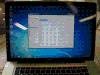
But ... on the RV building front, today was a day to mess with the
VP-X. I got to benefit from some of the cool/advanced capabilities
already. I had to finish running a pair of ground wires first (one for
the A supply bus, and another for the B supply bus). With that done
and the main power re-attached to the power input of the VP-X I
engaged the master and saw the ethernet connector LEDs start to blink.
I connected the laptop to the VP-X with the supplied crossover cable
and requested a connection, and got it. Wow!
I want to note that I am running the Vertical Power configuration utility
under Windows7, which is running in a virtual machine on my Macbook Pro.
It worked like a champ.
I was able to walk through the configuration of the box using my load
planning worksheet with no trouble. Everything played nicely. Then it was
time to try engaging the starter contactor. NOTE: I had disconnected the
cable from the starter itself as I do NOT want to have a prop start to
swing in the garage!! Its going to stay like that until I move to the
hangar, too (and even then may stay disconnected for a lengthy amount of
time).
I had checked that I had 12v at my start pushbutton, then pushed the
button. Nothing. Well, no "thunk" like I was listening for. Double-checking
I had power at the pushbutton I _then_ discovered I didn't. Looking at
the status page of the configuration program my "Starter" output was
showign a fault! It claimed I had a short circuit! Wow. I reset it, and
tried again, and got the same result.
After a little headscratching the only obvious probably could be the
spike catcher diode. And ... yes ... I installed it backwards. Without
the VPX I might have made smoke. As it was, it was a well controlled
non-event. Way cool.
I pulled the diode for now (will replace it when I get my hands on another
1N5407 diode as mine has different size ring terminals on each end so
it couldn't just be turned around). With that straightened out I got
the "thunk" I was looking for, and 12v at the end of the fat wire out
near the starter. That, too, was way cool.
I also spent some time fiddling with the latest PDF from Paul at SteinAir
so I could get a full-size printout of the thing. With a bit of fiddling
(edit out some stuff not needed to get the height down, and rotate it
90 degrees) it printed fine on the large-format printer at Staples. It
cost me a whopping $4.11 to print. Well worth it. :)
Time : 3.75 hours |
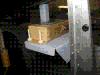
| Stick Grip Wire Termination Block |
May 15, 2011 |
|
Today is going to mainly be a non-airplane-building day again, but I did
get a little time early this morning to work on stuff. One of the issues
I've fretted over is how to terminate all my stick grip wires. I need to
tie pilot and co-pilot sticks together and then route a single bundle
forward. (Ok, I guess I could have run two bundles forward, one per
grip, but I'm trying to avoid doing that because my wire pass-throughs
in the spar are already pretty full.) I bought some terminal blocks but
they don't have a convenient number of positions, and they are hugely
bulky. So I've resisted using them. But I also bought some fast-on
adapter tabs and from there an idea germinated.
What I'm doing is using a bit of lexan bought at Lowe's and am pop-riveting
rows of the fast-on adapters along that strip of plastic. Since the fast-on
tabs come off at a 45 degree angle I can gang a pair together at each
position and end up with room for four wires to be tied together (though in
this case I only need three). I can create two rows of five each, and can
stack them to make a very compact termination bundle.
I got the lexan pieces drilled today, and have started to pop-rivet the
fast-on tabs in place. I've got to stop now to go do family-duty, but will
share pictures when I'm done with this exercise. (Assuming it works out,
of course.)
Time : 2.25 hours |
| Panel Arrived |
May 20, 2011 |
|
My beautifully cut panel arrived from Steinair today, and I had to carve
out a few minutes to install it. The fit is perfect. I pulled out my old
panel blank (that came with the kit) and dropped in the new panel. The screw
holes on the sides were spot on, and the rivet holes for the reinforcement
angle along the top were perfect. I pulled the switchs out of the old
panel (of course) and dropped them into the new. I am well pleased. :)
I also got word back from Vertical Power on what might be causing my
problem with the wigwag, and Marc suggested I had not assigned one of
the devices being configured to a switch. I was _sure_ I had, but he was
right and one of the landing lights was _not_ configured to a switch. I
made that change, and was able to configure the wigwag with no problem
after that.
Time : 0.75 hours |
| ELT Remote Debugging |
October 31, 2011 |
Tonight I thought I'd spend a little time trying to debug a problem
with the ELT remote. The remote will trigger and reset the ELT, but
the red LED won't light when the ELT is triggered. We already swapped
the remote, and after discussions with Paul we thought the next step
would be to see if the issue was the cable. I got a cheap 4-wire phone
cable and tried it ... then realized it was a crossover cable and it
didn't work. No time like the present to press my RJ-11 crimper into
service, so I cut off one end, stripped it for a new connector, and
crimped one on. After making sure it was well-crimped, I plugged it
in and it worked like a champ. I now just need to cut down the cable
supplied by the vendor and crimp on new ends. Since I'm going to cut
it anyway, I want to re-route it through a better location taking
advantage of one end being cut off. It wasn't much progress tonight,
but that is better than no progress. :) Oh, and Happy Halloween!
Time : 1.25 hours |
| Avionics Arrived! |
November 21, 2011 |
|
The avionics from SteinAir arrived today! I had been watching the UPS
tracking site and knew that the boxes were out for delivery since early
this morning.
One box arrived badly beat up, and my wife had the presence of mind to
open it right there with the UPS dude watching. Fortunately everything
in the big box was fine. *whew*
My plan is to start installing avionics over the T'giving holiday starting
with mechanical installation. Things are getting exciting!
|
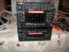
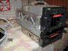
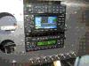
| Avionics Mechanical Installation |
November 24, 2011 |
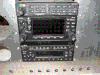
|
First things first ... Happy Thanksgiving, folks! With that out of the way
I can tell you that I launched into the mechanical work on getting the
avionics installed. Step #1 was to get the radios trays aligned. This was
done by the tried-and-true method of sticking all the radios into the
trays, aligning their fronts, then duct-taping the whole stack together.
That established the front-to-back alignment. (As you well know, trays for
different radios don't all line up the same, and if you just align the
fronts of the _trays_ you'll end up with a snaggle-tooth line of radios
once they are installed.)
I then pulled the little black boxes back out, stuck them back in their
protective wrappers, and put them back in their boxes. They are in storage
until the rest of the work is done. I then proceeded to remove the back
plates so I could cut the harness loose. Without that done it would be
murder maneuvering the trays around in the plane to get the side mounting
rails drilled and the sub-panel cut. I took a 4-inch long #0 phillips head
screwdriver and worked my hands into the trays to get the screws out. It
was not as bad as I thought it might be. Fortunately there are many open
spaces in the top/bottom of most trays, and that helped me get my hands
into the tight spaces. The SL-30 tray was the biggest pain, and will be
the biggest pain to re-install. However, Paul from Steinair has a special
long-handle custom-made screwdriver headed my way which he says makes the
re-installation of these tiny screws a snap. We will just see how that
works out.
I spent some time working on the fit of the trays in the panel. I screwed
in the mounting rails, and tried to slide the duct-taped collection of
trays into the panel. No joy ... which isn't unexpected. The trays vary
in width a bit, and I'm not surprised that one of them (the 430W tray)
is a tad wider than the opening. I broke out a file and started opening
up the panel ... going slowly so as to not take off too much metal. As
of noon the trays themselves fit, but can't get past the duct tape on
the trays. I believe I need a duct tape thickness of clearance anyway,
so am going to open things up a _tad_ more to accomidate. But since it
is noon, it is time for family-stuff here on Thanksgiving day. Hope you
didn't eat too much!
After the trays go in .... it'll be on to figuring out where to cut the
sub-panel. Scary!
Time : 3.5 hours |
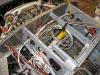
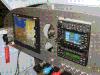
| Avionics Mechanical Installation Completed |
December 18, 2011 |
|
Today I opened up the panel a little more (to clear the short, but
not short enough) lower transponder tray. I slit some plastic tubing
to put around the opening as an anti-chafe measure. I finished installing
the tray backplates on the trays, and re-anchored the wire bundles to
the trays. I did a little in the way of other tidying up while the panel
was off, and then got the wife to help me lower the panel (with all the
harness bundles hanging off of it) into the plane. It all fit. Thank
goodness.
I wasted a lot of time head-scratching, discovering things I'd done earlier
wasn't quite going to work out as hoped, reworking those things, and other
delays. But, where I ended up looks really good to me so I'm not going
to complain.
Except ... I ache. Kneeling in the cockpit and crawling in and out and
in and out, took a toll. My back -hurts-, so I'm calling it done. I still
need to re-install the switches, and I may slide all the avionics in for
a static photo before I start running wires, but that can all happen at
some later date. Now I need a hot shower!
Time : 3.25 hours |
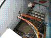
| Pitch Servo Wires Pulled / Ground and Power |
December 30, 2011 |
|
Yesterday was pretty much consumed by family activities (and going to
see a friend's propellor carving system ... yes, he has created a CAD
driven homemade CNC machine to carve a propellor, which was amazing to
see). In the morning I got out and started pulling out the old wires
and routing the new ones. As a note, all this re-routing of wires has
caused me to yank out (cut out, more accurately) some short pieces of
conduit which I had running under the fuel pump mounting plates. They
were a pain to pull out, and I should never have used them in the
first place.
In place of the conduit I have some large gauge plastic spiral wrap
which does a MUCH better job, and still provides anti-chafe protection.
And it will be MUCH easier to add new wires if/when I need. Lesson learned.
Pulling the new pitch servo wires proved to be a LOT easier than I had
anticipated. I lucked out. I still need to get the pinouts from Stein
but they are coming along with a few short cables I need that I got Jon
at Steinair to make for me. That won't get here until Tuesday, but that
is no problem. I still have plenty of other things to work on.
I also tidied up some of the wire bundles that I'm routing. This included
the OAT cable, the serial cable from the AFS to the VP-X, the servo
wires, and the AFS battery backup wires. I mainly now need to connect
the VP-X serial cable, the control-wheel stearing line, the PTT lines,
and all the power and ground connections.
This afternoon I came back and routed and terminated the ground wires. I
had to spend a little time thinking about routing options until I found
what seemed most ideal. I then routed them, terminated them on the ground
block at the firewall, and then secured them along the route. I probably
need to go tighten up the bundle in a few places (either with ty-wraps
or lacing) to make it a bit neater.
I also started routing the power and headset wires. I had been concerned
that the power wires might be too short and may need to be extended, but
that is not looking to be the case after all. I'll know more when I
finish the routing tomorrow. The one thing that may need extending are
the pilot side headset wires. They may be a TAD too short to allow for
nice tidy routing of the wires. I'll survive.
Progress continues to happen! :)
Time : 4.75 hours |
| Power Wires Routed (and a few Terminated) |
December 31, 2011 |
|
I got out this morning and started lacing wires. I'm rather getting into
the lacing, and am finding it almost as quick as ty-wraps. Not quite, of
course, but close. One thing I find annoying about ty-wraps is in some
spots it is hard to maneuver the pointy end into the "buckle". Bending
the stiff-ish plastic around the back side of wires and keeping it from
bouncing back while you try to maneuver it into the buckle can be tedious.
The waxed lacing stays put once bent around the back of a bunch of wires.
After that a quick tug and knot and you are done except for trimming the
spare lace off the ends. Anyway ....
I laced up the ground wires nice and neat, then started on routing the
power wires. I had not really done my homework on those wires and was
confused by a thing or two that I saw once I started looking at the
labels. A little investigation revealed all, however. I then divided
them up into groups based on which of the VP-X connectors they were
destined for, and took the first bundle (to the furthest-away connector)
and got them routed. This called for another adel, of course, and a bit
more lacing. But I connected the transponder, SL-30, and audio panel
power wires into the VP-X. I then ran out of time and had to call it
done for the day.
My plan is to very methodically get everything connected, then check the
power one pin at a time to insure that everything is kosher. Only then
will I start to power up boxes (cheapest first) one at a time. But I
_am_ getting close to that exciting day.
Oh ... and Happy New Year, everyone!
Time : 3.75 hours |
| Power Wiring Continues |
January 2, 2012 |
|
Yesterday I was down with back pain ... and, no, it wasn't a hangover
either! :) I only had about 2 glasses of champaigne on New Year's Eve!
Today we have last-day-of-the-holiday-break family plans, but I did
get out and do a little wiring work. I realized I had run the power
for the SL-30 directly to the VP-X, and that the intention had been
to have it route through a backup power switch. So I used the VP-X
pin extraction tool (a little piece of wire) to pop out the pin and
re-route the wire to the backup switch.
The plan is to have power be
normally routed from the VP-X, but in the case of VP-X failure the
DPDT switch can be moved to provide power off of the switched (i.e. on
the near side of the battery contactor) battery buss. The "backup"
can also be used before engine start to get ATIS/AWOS information
without bringing up ALL the avionics. So the flow will be to power
on the master (bringing up the VP-X and EFIS), then switch to the
backup position to power up the SL-30, get ATIS/AWOS, switch back to
the normal position on the backup switch, then start the engine. Once
the engine is running the avionics master (i.e. the VP-X switch that
directs the VP-X to bring up all the avionics related output pins) is
switched to bring everything else up. This serves two purposes. It
will reduce demand on the battery before engine start, _and_ will
have me exercising the backup circuit before every flight as a
preflight measure.
Currently only the SL-30 is going on the backup, though I have
provision for two devices. The EFIS will have a battery backup, as
will the Gemini (when it is installed). So they are backed up in
a different manner and can operate even with a full electrical
failure. I'll also have an Icom antenna switch-box to allow me to
connect my handheld radio to the COM #2 external antenna, and a
backup handheld GPS. Can I still get stuck in the clouds without
a way to communicate and navigate? Maybe. But I think this plan
has me fairly well covered.
After re-working the SL-30 wiring, I came back in the evening and
pushed forward on making the rest of the connections. I got them
all mostly done, with only a few odds and ends left. I need to add
the EFIS backup power pin into the DB-25 for the EFIS, and need to
wire the backup power switch on the panel for the SL-30. All in all
it has ended up being a very productive day.
I still need to mount the ARINC box, mount the Icom antenna backup
switchbox, and terminate the coax connections on the radios. I also
need to fabricate the GPS antenna mount and get the antenna mounted.
So I have another good bit of work left, but I'm getting close to
the end.
Time : 2.5 hours |
| ARINC Non-Installation! |
February 5, 2012 |
|
WHAT A FRUSTRATING DAY! I started down one track on mounting the ARINC
box, and then hit a total brick wall. This was after drilling and fitting
some angle to the ARINC box itself, removing the VP-X to get to a tight
spot, then discovering that the tight spot was TOO TIGHT to be reasonable
long term. Once the top skin got closed in I'd never be able to get my
hands on that box again. So, I finally gave up in disgust after standing
there for a long time looking at alternative locations.
Since I wanted to accomplish SOMETHING positive today, I installed the
EFIS. It needed to go in, and I was tired of the various dangling cables
hitting me in the face. Running against the trend for the day (i.e. not
having anything work out) the installation of the AFS-5600 went quite
well. In fact, cables that I had run ages ago ... and in which I took
my best guess as to the correct length ... fit _perfectly_. They are so
good a fit it is almost like I had the EFIS installed while running the
sensor wires. Wow.
After calling it done for the day, I had yet another thought on where/how
I can mount the ARINC box. I almost want to run back out to the shop and
see if what I'm proposing will really solve my problems. But, I am going
to wrap it up for today as I am _hurting_ from all the laying under the
panel I did! I am _not_ looking forward to re-mounting the VP-X. *groan*
Time : 3.5 hours |
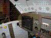
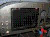
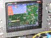
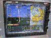
| Powering Up Avionics |
February 12, 2012 |
|
Today I started with powering up the first of my avionics (in the panel, at
least, as the VP-X has been powered up for a long time now). Since the
heart of the system is the AFS-5600, and since the wiring harness was done
by SteinAir, and since it has been powered up on the bench at SteinAir, and
since it isn't on the "avionics master switch", I decided to bring up the
EFIS first. I was terrified, but it had to happen sometime. As it turns out
it came up without a hitch.
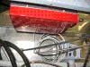
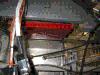
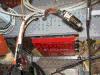
Ok. There is a lot of red being shown, but that is because nothing ELSE is
installed and powered up at this point! The display is a little messy due
to the fact I've not pulled off the protective platic yet. That will stay
on for some time to come. But you can't imagine how thrilled I am to see
this puppy come to life! Wow. Now .. time to power up a few more things to
see if my panel really is going to come alive.
I then took the next step, configured the EFIS to talk to a VP-X Pro, and
confirmed that the AFS-5600 and the VP-X were going to be happy together.
It worked like a charm, and now I have control of the VP-X from the EFIS
screen. I then installed the audio panel, and brought it up. As best I
can tell it works fine (little lights turn on, etc.). Now it is time to
connect a few coax cables .. mainly on things that transmit, in case they
decide on a whim to transmit. I want there to be a load on the output of
any transmitter that tries to pump out some power.
One last little test had to do with making sure the Bluetooth connection
to the PMA-8000BT audio panel worked. I paired it with my cell phone and
initially could only get music to play, but no phone connection. Then I
reconfigured my cell phone to include the phone functionality in the
BT connection ... the default was music-only. I was then able to make a
call and converse with a friend via my headset and the audio panel. These
tests served also to confirm that my mike and headset jacks were wired
correctly. One last test was to trigger the PTT, and see the "transmit
in process" indication on the audio panel ... the selected COM LED
blinking. Everything worked. That just rocks. :)
Time : 3.5 hours |
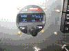
| More Powering Up Avionics |
February 19, 2012 |
|
Today was GNS-430W day. I finished installing the GPS antenna, and
then installed and powered up the GNS-430W itself. There were a few
small issues. It looks like when I did the original aligning of the
radio trays I didn't have the 430 in all the way! I had to pull it
forward by about 1/4" to align with the rest. Fortunately that was
enough of a change that I didn't have to add a patch to the mounting
angles. Just pulled it foward the requisite amount, drilled four holes,
and I was good to go.
Another issue is that the 430 is not acquiring satellites. I don't
know if this is due to a problem in my antenna, coax, or the fact that
I'm in a garage (with a 2nd floor above it). The last issue is that
I am not getting any sidetone when transmitting on the 430. I get
sidetone fine from the SL-30. I'll have to talk with the folks at
SteinAir about that .. but I'm sure it can be resolved.
The only piece of avionics left (that I have taken delivery of, at
least .. the Gemini PFD is still not delivering yet) which is not
installed and powered up is the autopilot. I have to dive back into
the tailcone to get to the servo to complete that work. Maybe that'll
happen today, but not likely.
Time : 4.25 hours |
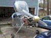
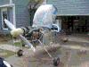
| GPS Validation / Autopilot Install |
February 26, 2012 |
|
Yesterday was consumed by taking care of a backlog of stuff I needed to
address around the house. I decided to get the entire backlog out of the
way so I could then do airplane-stuff with a clear conscience! :)
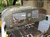
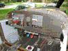
Step #1 today (since it is nice and sunny out) was to roll the fuselage
out into the driveway to confirm that my GPS was working. I needed a
good view of the sky so that it could acquire satellites. It got itself
oriented in very short order, and communicated the position successfully
to the EFIS as well. I was able to pull up the charts for the local area
(now that the EFIS no longer thinks I'm out in the Minneapolis area). I
also adjusted the very weak sidetone on the 430, but I'm not sure it
doesn't need a bit more work. I'll talk to Stein about that on Monday.
While the fuselage was out in the sunshine I took the rare opportunity
to really sweep out the shop. Man ... it was filthy. It won't stay clean
long but I'll enjoy it while it does. :)
I spent a little time revisiting the Gretz Aero heated pitot. There
were labels on the wires which were just masking tape and ball point
pen which I replaced with printed heat-shrink tubing. I also went ahead
and flaired the end of the pitot tube (remembering, thank goodness, to
put the requisite fittings on before flairing the end!). Now that I
am refamiliarized with how that install works I'm putting it back in
the box until we head to the airport for final assembly.
Using pin-outs sent by SteinAir I connected the pitch servo wires to
the connector, and then installed the connector on the pitch servo.
I also got the autopilot head installed, which is the last piece of
avionics until the TrueTrak Gemini PFD is available and delivered.
Now with all that installed I am spending a little time tidying up
the wiring. This means it is adel-clamp/lacing/zip-tie time.
Time : 4.25 hours |
Total Time : 250.50 hours
|
|
![[ The Frye RV-7 Project ]](images/frye_project_banner.png)